Simulation Workflow
Signal Integrity in CAN
A modern automobile may have as many as 50 electronic control units (ECU) for various subsystems, which must be investigated onto EMC problems such as crosstalk and signal integrity.
One of the known vehicle buses standard for data transfer is the CAN bus system. Controller Area Network (CAN) is a multiplexed wiring system used to connect intelligent devices such as Electronic Control Units (ECU’s) onto vehicles, allowing data to be transmitted in a low-cost and reliable manner.
Within EMC Studio currents and voltages are calculated in the time domain for CAN system transceiver and receiver.
Problem Definition
CAN device in addition to the main part usually contains countermeasure modules, which are stabilization networks and common-mode choke. Stabilization network smoothes CAN signal by removing undesirable ringing. Common-mode choke usually consists of coupled inductances, and this module cancels out unwanted common-mode currents in the system, decreases the level of radiation and improves immunity.
TWP cable connecting CAN devices is located above the ground plane. Currents and voltages are calculated in the time domain for CAN system transceiver and receiver.
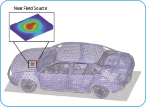
Near Field Source
Electronic components are required to comply with the global EMC regulations to ensure failure-free operation. Currently, EMC measurements in certified institutes are mandatory to certify performance complies with regulations. Since these measurements are performed at the end of the product design process, failing an EMC test can imply a costly redesign. However, the process that is outlined in this paper enables EMC testing to be performed earlier in the design cycle.
- The simulation model of complete PCB can be substituted by equivalent Near Field Source
- Required information for Near Field Source is electromagnetic fields produced by ECU on surrounding closed surface
- Electric and magnetic fields for Near Field Source can be calculated without the presence of most part of passive objects

Conclusions
According to the performed investigation, the main conclusions are:
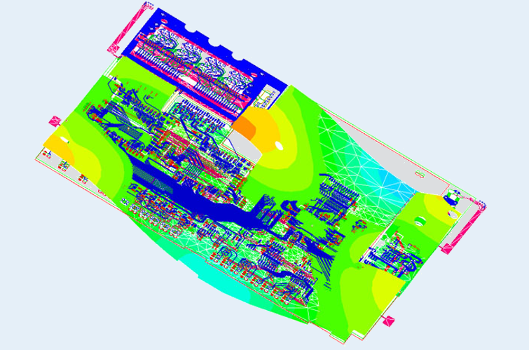
- Component level simulation of PCB is done using ANSYS SI-Wave for major preprocessing and for calculation of EMI/EMC of PCB ports and elements
- PCB can be analyzed on system-level, as in the described example of EMI/EMC in automotive systems using Near Field Source feature

Contact Us: info@croydonservice.com